Have you ever had your brewing day delayed because somehow, even with all your ports open, your wort pump does not seem to prime properly?
Perhaps you were transferring wort from your kettle to a wort chiller and you wanted to remove residual liquids from the transfer hoses. Most of us typically try to remove a hose at some high point in our circulation path to let the air push its way through. This solution, along with the burning hot 200 degree sticky wort seeping from the disconnected end (you have in your burnt hand), typically ends up on the floor or your equipment causing a sticky unsanitary mess. Sound familiar?
The cause of this cavitation problem is typically due to an air bubble or pocket of air that is stuck in the head or impeller of the brew pump.
Magnetic clutch pumps have an impeller which is similar to an air fan or water prop, except they have flat veins and are enclosed in a housing (the pump head) with entrance and exit ports. This impeller is designed to push liquids, not air. A very simple way to understand this is a liquid does not compress – air does. As the impeller turns, the bubble compresses, cavitation occurs, and it cannot move the liquid it is trying to displace out of the exit port. Once the air pocket has moved past the impeller to the exit port, the liquid will enter the impeller chamber and continue onto its destination in your system.
Our solution for cavitating brew pumps is a controlled point of exit of the air via our new bleeder valve style Purge & Waste kit. By placing our kit on the outbound port of your pump, you simply open the valve and purge the bubble/air pocket from the pump housing. Once open any trapped air, hot wort, or rinse water can safely flow to a vessel to be disposed (not on the floor).
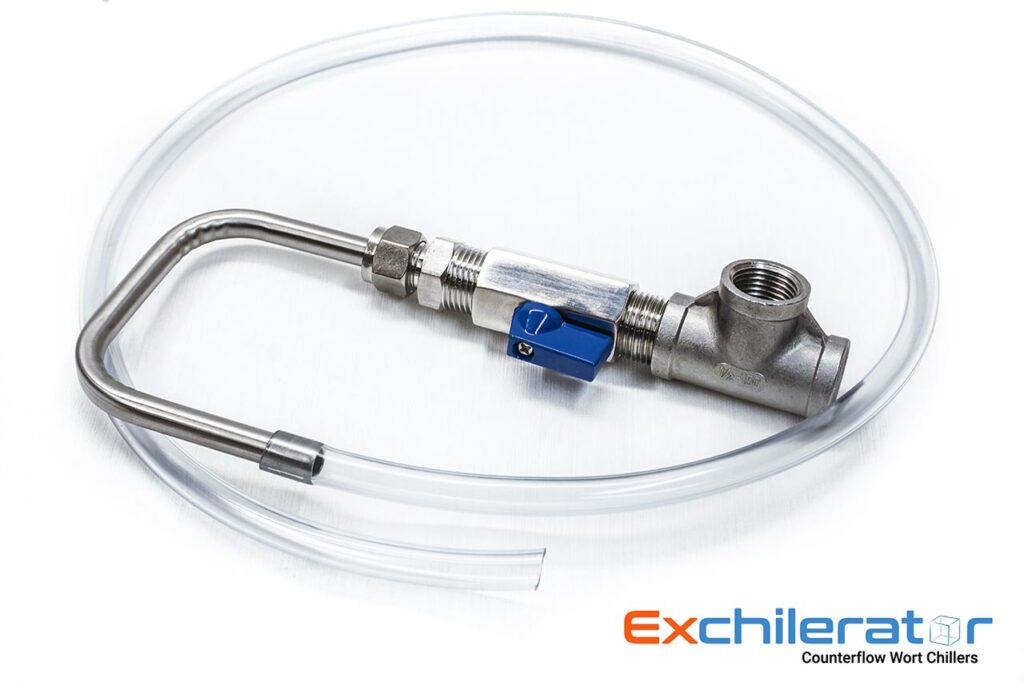
The Waste and Purge kit consist of the following:
- ½ inch 304 Stainless FNPT (female national pipe thread) Tee. Anatomy of a Tee. Tees have two flow directions. The horizontal top of the {T} is called the run, and the vertical of the {T} is called the branch. This is important to know because depending on how you mount the pump will dictate whether you have the run or the branch venting up.
- ½ inch 304 Stainless Close nipple. Close is the actual length – it means the opposing threads are close or touching.
- Small ½ inch 304 Stainless ball valve.
- ½ inch MNPT (male national pipe thread) x ⅜ compression fitting with a Delrin ferrule.
- 6 inch x ⅜ ID 304 stainless Purge Tube with 2 foot vinyl Waste hose.
- Roll of Teflon threading tape.
Horizontal Installation:
- The first part to install is the Tee. Looking at the pump head end of your pump, if the threaded exit end is horizontal, install the Tee on a run end and finish with the branch up so that the air bubbles will float up the branch to the valve and liquid will continue out the other end.
- Thread the close nipple into the branch of the Tee.
- Thread the valve onto the nipple. Try to tighten so the valve handle is in a convenient position to operate.
- Thread ½ male x ⅜ compression fitting into valve.
- Warm an end of the vinyl in hot water and slide over the ⅜ stainless purge tube about ½ inch.
- Slide one end of the stainless purge tube into nut and ferrule to the stop machined into it. Snug up the compression nut until Delrin ferrule is causing enough friction to keep the tube in a position you desire.
Vertical Installation:
- The first part to install is the Tee. Looking at the head end of your pump, if the threaded exit end is vertical, install the Tee on a branch end and finish with the other run end up so that the air bubbles will float up the run to the valve and liquid will continue out of the branch.
- Thread the close nipple into the run end of the Tee.
- Thread the valve onto the nipple. Try to tighten so valve handle is in a convenient position to operate.
- Thread ½ male x ⅜ compression fitting into valve
- Warm an end of the vinyl in hot water and slide over the ⅜ stainless purge tube about ½ inch.
- Slide one end of stainless purge tube into nut and ferrule to the stop machined into it. Snug up the compression nut until Delrin ferrule is causing enough friction to keep the tube in a position you desire.
Notes:
Refer to #1 in parts. Anatomy of a threaded Tee, Branch and Run explained.
Teflon tape should rolled on clockwise and started flush with end of threads. About 3 wraps should be sufficient.